In previous articles, we’ve explained what wheel alignment is, why it is important and how to properly adjust it.
In this piece, we will look closer at the causes of incorrect wheel alignment, the main consequences, and what should be considered to avoid these issues and prevent the potential costs that are often linked to them.
Wheel alignment is critical to the proper operation of your car’s steering and suspension system, and ensures the whole system can perform safely and accurately. The angular parameters for correct alignment are defined by the vehicle manufacturer.
These angles are:
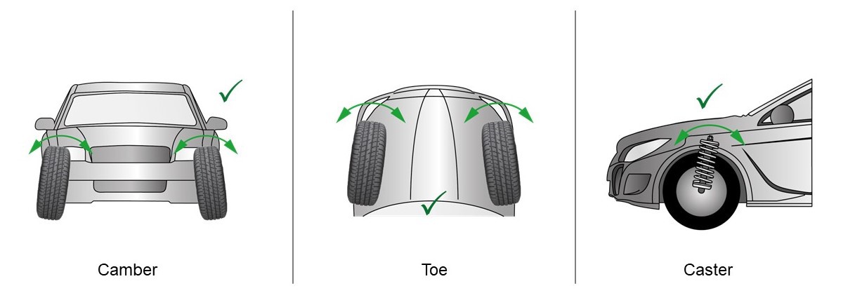
However, poor road conditions, parking manoeuvres and natural wear of mechanical components within the steering and suspension system can lead to misalignment.
Returning the system to its optimal geometry as defined by the manufacturer can restore maximum control and make the steering more comfortable and precise. This, in turn, can extend the life of your car’s steering and suspension components, and can protect your tires from uneven and premature wear.
The most commonly affected parts are:
- Wishbone/control arms and bushings
- Ball joints
- Axial rod with tie rod end
- Top strut bearings as part of Mounting Kit
Before going into detail of these parts and their potential failures, let’s look at the main components of front axle suspension system:
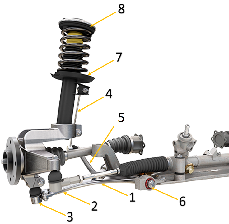
- Axial rod
- Tie rod end (Steering ball joint)
- Wishbone´s ball joint (Suspension ball joint)
- Stabiliser link
- Stabiliser/ Sway bar
- Bushings
- Strut (spring+shock absorber)
- Mounting Kit
WISHBONE/CONTROL ARMS
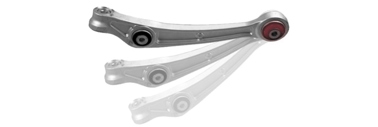
Wishbone/Control arms are attached to the chassis by elastic rubber bushings and to the steering knuckle by ball joints. The rubber bushings – usually two in the case of trapezoid wishbone arms, or a single bushing in the case of track control arms – consist of a metallic sleeve housed within an elastic material, through which passes a bolt to secure it to the chassis.
This type of bushing allows these components to be attached to the chassis in such a way as to absorb the oscillations and vibrations of the suspension without transmitting them into the cabin. As a result, they must be resilient enough to withstand the forces exerted on them by the suspension over the course of many thousands of miles.
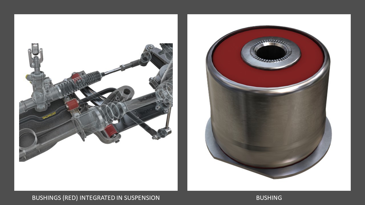
Some suspension set-ups may have as many as 100 separate attachment points, and often deploy a mixture of ball joints and rubber bushings. More advanced suspension systems provide greater comfort and manoeuvrability, but that may also introduce additional points of failure. Failure of these parts may result in unwanted noise, incorrect wheel geometry, uneven tire wear, or steering that pulls to one side during driving or braking.

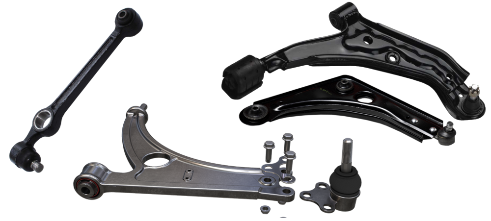
WISHBONE AND TRACK CONTROL ARMS WITH INTEGRATED BUSHINGS AND BALL JOINTS
The most common failures are often caused by natural wear due to environmental effects such as high temperatures and ozone levels that can vitrify the rubber making it crack, as well as salt, mud, dust, impact damage and even incorrect installation.
*Garage Gurus tip: Use only quality MOOG parts, observe the markings on the bushings, and during installation maintain natural height position of wheels in respect to the ground and then tighten components to the specified torque.
Check the pictures below.
How to correctly install asymmetric bushing
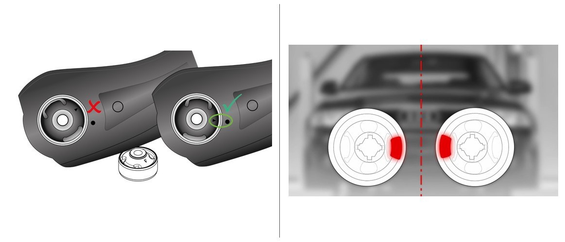
DON'T FULLY TIGHTEN PARTS UNTIL THE VEHICLE RETURNS TO ITS NATURAL POSITION ON THE GROUND!
This ensures no excessive stress is placed on the rubber, extending the working life of the bushing.

BALL JOINTS
Ball joints are a crucial element in achieving angular movement. These connecting components allow controlled movement of the suspension arms and the steering knuckles without transferring loads to the steering mechanism. There are two types of ball joint depending on whether they are loaded by the weight of the vehicle. Steering ball joints or tie rod ends are not designed to carry the weight of the vehicle, since their only function is to rotate the steering knuckle in response to movements of the steering mechanism.
Generally, ball joints can be found in steering and suspension parts such as stabilizer links, track control arms, axial rods and tie rod ends.
Every ball joint consists of multiple components: a ball joint stud, forged and machined steel housing, special polymer or powder metal bearing and a protective boot made of rubber or thermoplastic polyurethane which keeps the grease inside and prevents the ingress of dirt and water.
MAIN PARTS OF BALL JOINT
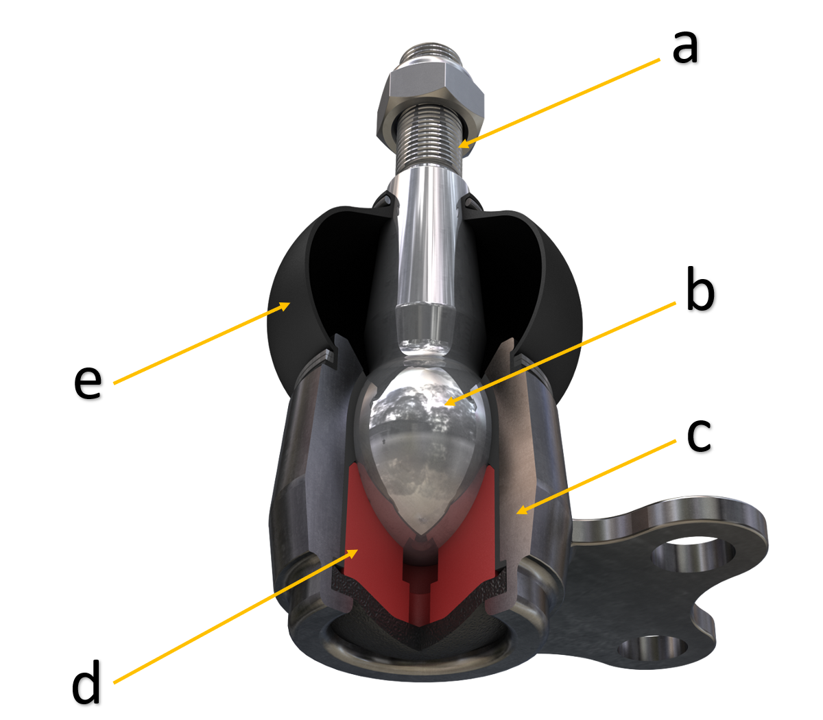
b) Ball section of stud
c) Housing
d) Bearing
e) Dust boot
All these elements are wear and tear items and are subjected to high loads that create strong rotational movements as well as high radial and axial forces. As a result, they are perfect candidates for failure.
There are many possible modes of failure, from protective dust boot damage, excessive wear of the bearing, incorrect installation, mechanical impact, rust, salt and mud from the road, and so on.
Wear of the internal bearing is gradual and, in many cases, hard to notice. Eventually this will lead to play within the ball pin inside the bearing.
Solution:
- On the first sign of failure, replace the faulty part. Remember: always replace steering and suspension parts in pairs.
- Perform professional wheel alignment.
- Always use a torque wrench and respect the torque values specified by the manufacturer.
- Always use new bolts and nuts, as rusty parts can easily break.
- Do not reuse “nylock” or self-locking nuts.
- As these parts are safety critical, always choose quality components. MOOG recently upgraded the parts in their ball joints with this in mind.
DO NOT use pneumatic wrenches to tighten the securing nuts, as this can quickly exceed the specified torque values as well as damage the joint by causing the ball to rotate at speed within its bearing.
AXIAL ROD WITH TIE ROD END
Axial rods link the steering rack to the tie rod end. They are the perfect complement to the tie rod end that is attached to the steering knuckle, and allow the vehicle’s wheels to move smoothly in an upward and downward motion.
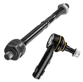
They are called “axial” because they are mounted in the same direction as the steering rack rod, as if they were an extension of it.
After mounting these important units, the steering alignment must be checked. In newer vehicles, an ADAS calibration may also be required.
Failure to do so may change the toe angle, putting at risk not only the driver’s ability to control the vehicle, but also the lifetime of the tires due to the dragging effect caused by the incorrect geometry.
TOP STRUT BEARING (AS PART OF MOUNTING KIT)
In vehicles that use MacPherson suspension, these have the purpose of attaching the chassis to the steering knuckle-wheel set-up, which transmits the entire weight of the vehicle. Since the wheels must be able to rotate from one side to the other, the use of some type of joint between the chassis and strut connected to the steering knuckle attachment is required. This is the purpose of the top strut bearings.
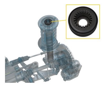
Mounting Kit’s bearing - located on the top of the strut
This type of bearing is installed on the upper part of the strut piston rod. When the steering moves from one side to the other, the bearing allows full rotation of the strut with respect to its anchor point on the chassis.
The bearing is part of the upper mounting kit (MK), along with a strut rubber bushing that absorbs vibrations while ensuring that the wheels have the best contact with the ground.
*Garage Gurus tip: Never reuse old mounting kits. Always change them in pairs every time you change the shock absorbers. Their expected lifetime is around 80,000 km.
Always respect the service manual instructions from the vehicle manufacturer. There are some models where mounting kits may differ slightly, and correct installation is critical to ensuring good wheel alignment.
CONCLUSIONS
- Failure or incorrect installation of these parts may cause incorrect wheel alignment in terms of camber, toe, or caster.
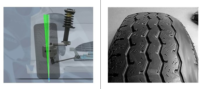
- Incorrect camber can cause internal (negative camber) or external (positive camber) wear on the tire sidewall.
- If the camber is too high (positive), it will cause wear on the outer sidewall (see picture below).
- In the opposite situation (negative camber), it will cause inner sidewall tire wear.
EXCESSIVE CAMBER:
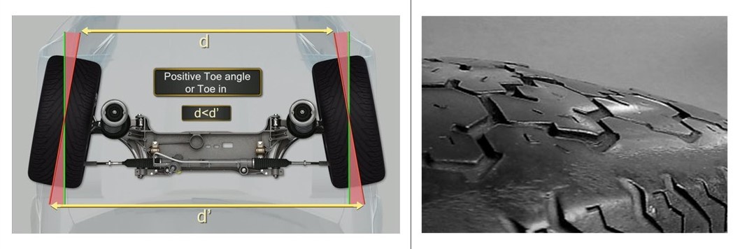
Incorrect toe angle is also known as "bevelling".
If the toe is incorrect, the tires can roll with constant slippage (lateral pull) along the road causing severe premature wear.
Examples of toe angle alignment:
*Garage Gurus tip: Having the toe angle out of tolerance by just 3mm can cause slippage of half a metre to the side over a distance of 1km.
Many new cars are now equipped with a range of Advanced Driver Assistance Systems (ADAS). These systems use a wide variety of sensors such as cameras, radar and lidar to detect obstacles and measure the vehicle’s position. The system can then respond accordingly to preserve occupant safety.
Incorrect wheel alignment may impact the ability of ADAS to function correctly. There are three types of systems that are particularly reliant on correct wheel alignment:
- Lane keeping assistance (LKA)
- Lane departure warning (LDW)
- Lane centring assistance (LCA)
Although each system has a different focus, their main objective is to keep the vehicle within the driver's intended lane of travel.
Steering wheel angle also plays a significant role here. Even before modern driver assistance systems, safety on the road would be easily compromised if the steering wheel angle wasn’t set to match the alignment of the road wheels.
Now that ADAS features respond automatically with movements of the steering wheel, the danger of incorrect alignment becomes even more serious. Any time a wheel alignment is performed, you must check that the ADAS settings are validated and recalibrated if necessary. It is crucial to ensure that all vehicle sensors are in-sync according to the vehicle manufacturer’s specifications.
Here are some examples of repairs that, on a vehicle fitted with ADAS, will require calibration:
- Wheel alignment
- Suspension work
- Headlamp alignment
- Windscreen replacement
Proper understanding of how these parts function, the use of proven replacement parts from a brand such as MOOG, and carefully following the specified installation procedures and torque values will provide many years of quality service and ensure the satisfaction of your customers.
Want to know more?
Interested in knowing more about steering and suspension system and tips on servicing it? Check our technical data sheets page and download the relevant files.
Enjoy access to free online steering and suspension courses by registering for our e-learning platform or visit the Garage Gurus YouTube channel.
This article is for informational purposes only. We are not liable for any damages resulting from your reliance on this content. This check list only provides general advice and cannot be referred to as a completed and final guide to each driver's responsibility to ensure that her/his vehicle is in a proper working condition and ready for use on the road.

 English